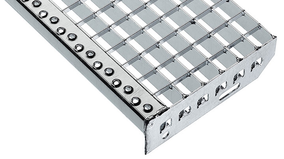
Since the early 1960s, Lichtgitter has been supplying its customers, using continuously improving technology, with thousands of square meters of pressed floor gratings. In addition to their common use in industry and construction, these floor gratings are also used as façade elements of buildings, covers for convectors and air-conditioning units, interior suspended ceilings, etc. Pressed floor gratings are manufactured and supplied in steel, stainless steel and aluminum versions.
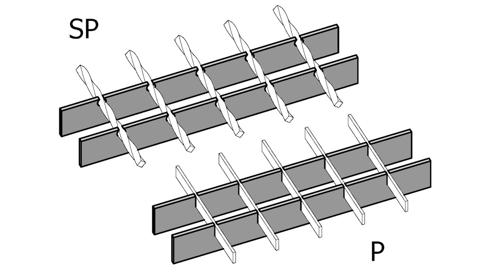
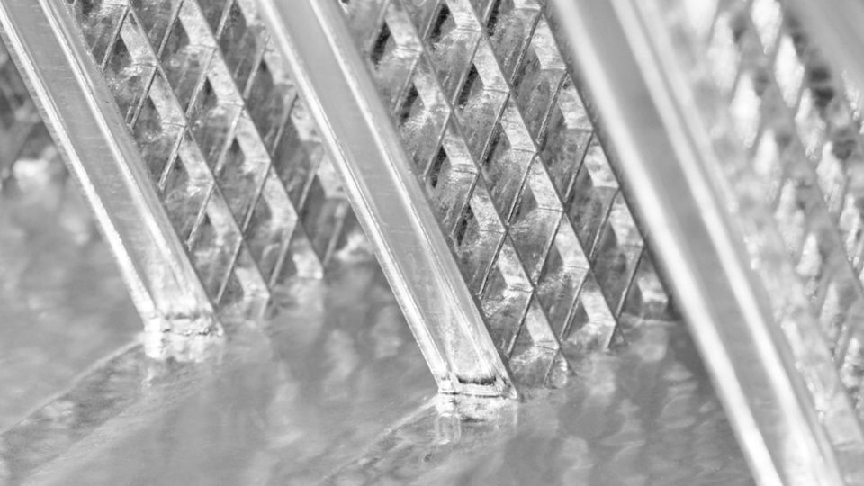
Design principle of pressed floor gratings
The load-bearing structure of the grating consists of steel bearing bars, whose mutual position and stability are ensured by cross bars. In addition to maintaining the position and stability of the bearing bars, the cross bars also serve to partially redistribute the load to bearing bars outside the directly loaded area. This fact is also taken into account in the structural calculation for grating dimensioning.
")
Manufacturing technology of pressed gratings
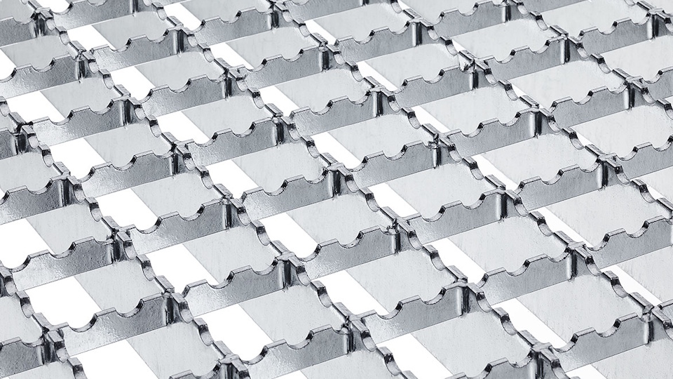
Cross bars are pressed into the bearing bars with prepared conical or otherwise shaped grooves under high pressure (up to 20,000 kN). The high pressing force and the special shaping of the grooves in the bearing bars ensure a rigid structure resistant to torsional stress, thanks to which the load is favorably distributed and even additional small cut-outs can be made on site without significantly reducing the load-bearing capacity of the grating.
Production program – manufactured according to DIN 24 537-1
Material
Steel S235 JR (according to EN 10025-2:2004), S355JR; stainless steel X5CrNi18-10 / 1.4301, X6CrNiMoTi17-12-2 / 1.4571; aluminum AlMg3G22, AlMg1F15.
Production dimensions
Pressed floor gratings are manufactured in a wide range of bearing bar and cross bar dimensions to provide the optimal type of grating. Gratings are manufactured to measure; in the direction of the cross bars (grating width), the standard dimension is 1400 mm, the maximum dimension with machine edging (more economical) is 1600 mm, and with manual edging up to 1750 mm. The maximum grating length (panel) is 3000 mm.
Example of grating layout:

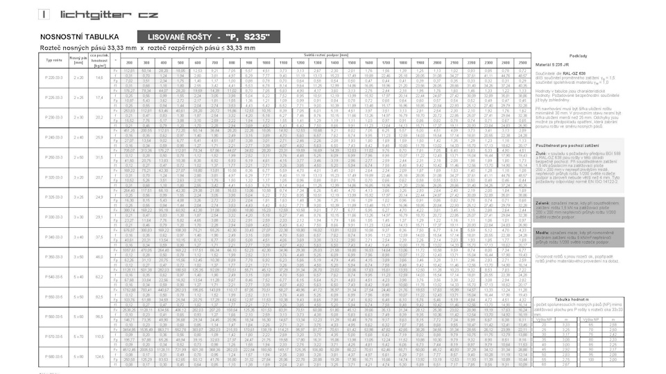
Standard production range
Center-to-center spacing of bearing bars and cross bars – mesh size
| Bearing bar spacing | Cross bar spacing |
| 22.22 mm 33.33 mm 44.44 mm 66.66 mm | 11.11 mm 16.65 mm 20.00 mm 22.22 mm 25.00 mm 33.33 mm 40.00 mm 44.44 mm 50.00 mm 55.55 mm 66.66 mm |
Values in bold comply with DIN 24531-1.
Other mesh spacings available upon request.
Bearing bar dimensions
| Bearing bar height [mm] | Bearing bar thickness | |
|---|---|---|
| 2 mm | 3 mm | |
| 20 | o | o |
| 25 | o | o |
| 30 | o | o |
| 40 | o | o |
| 50 | o | o |
Other bearing bar heights and thicknesses (up to approx. 200×10 mm) available upon request.
Additional production program
Solid gratings (same height of bearing and cross bars), heavy-duty gratings, drainage channel covers, convector covers, façade gratings, sunshades, etc.
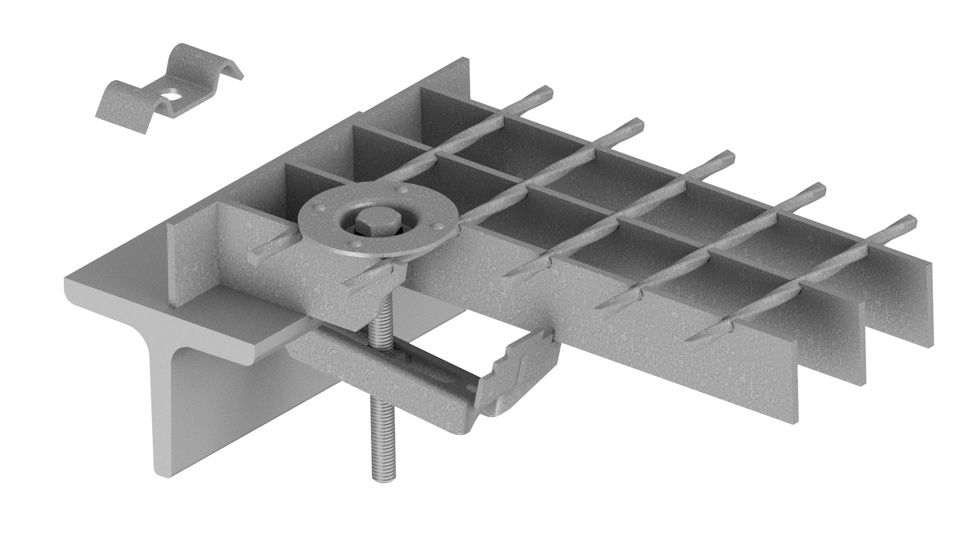
Edging
Pressed gratings with bearing bars 20 x 2 mm up to 40 x 3 mm are edged with flat bar or special Lichtgitter profiled flat bar. If the bearing bar dimension exceeds 40 x 3 mm, the grating is edged only with flat bar.
Grating designation
| Pressed grating – P | P | |||||||
| Bearing bar 30×3 mm | 330 | |||||||
| Bearing bar spacing 33.33 mm | 33 | |||||||
| Cross bar spacing 11.11 mm | 11 | |||||||
| Edging bar 30×3 mm | 3 | |||||||
| Designation: | P | 330 | – | 33 | / | 11 | – | 3 |
Anti-slip design of pressed floor gratings
– more information here.